|
Updated: 23 January 2001 In response to the number of emails I'm receiving from people who have designed their own pulse jet or built one from the many plans that are available on the Internet and are having trouble getting it to run I have added The Pulse Jet Troubleshooting Guide and an explanation describing how these engines actually work.
Updated: 22 January 2001 The power output seems to be a little more than was predicted and it has excellent starting and throttling characteristics. I hope to post some pictures and video to the site in a week or so. I will also be fitting it to the gokart which is currently nearing completion. Many visitors to this site have asked how fast a gokart with such an engine would go -- we will soon find out! Also note that due to the astonishing demand (which presently exceeds my capacity to manufacture them) for the pulse-jet kits I will shortly be offering plans and instructions for people who are prepared to build their own engines from scratch and have (or have access to) the necessary equipment. Included will be a CDROM containing the plans, documentation and about 20 minutes of video in MPEG format, showing the construction and operation of these engines.
My First Pulsejet Project
Not having had any formal training in metalworking or engineering, this meant I had a steep learning curve ahead of me. Fortunately, almost two years later, I'm now significantly more competent and capable in this area.
Updated: 16 October 1999 There'll be another installment shortly when I hope to add the streaming video and talk about the next version -- which will be bigger, louder and hopefully -- a constructional project with plans for those who want to also build one of these really interesting little engines.
Updated: 26 September 1999 More details of this part of the project can be found on the reed valve page Note that I'm going to re-organise this site a little so as to put each weekend's work on a separate page to avoid ending up with pages that are so large they take ages to load. In the meantime, please feel free to tell me what you think of the project and this website. I'm always keen to hear of good ideas as to how I can do a better job of either. Just drop me a note.
|
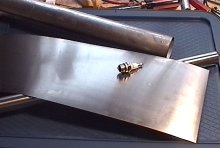
 The front end of the engine is now almost complete. I have cut out the
reed valve, turned up a retaining washer/seat and tapped the hole in the
back of the venturi section to accept a 4mm hex-head machine screw that
holds it all together.
The front end of the engine is now almost complete. I have cut out the
reed valve, turned up a retaining washer/seat and tapped the hole in the
back of the venturi section to accept a 4mm hex-head machine screw that
holds it all together.
Updated: 18 September 1999 Today I finished turning up the body of the intake assembly -- a process which
involved center-drilling and tapping the back face so that the intake reeds and retainer
can be bolted on.
Today I finished turning up the body of the intake assembly -- a process which
involved center-drilling and tapping the back face so that the intake reeds and retainer
can be bolted on.
The front-end of the intake body has a tapered hole which creates a venturi section where the fuel jet will sit. The initial size of this air-intake hole may be a little small for maximum power but I've decided to err on the side of better fuel draw by having a higher air velocity through the venturi. Once I have this version of the engine running I'll be playing around with the construction of a tuneable intake venturi and a throttle. I also turned down a lip on the intake by the wall thickness of the combustion chamber tube so it will fit inside. The intake assembly will be affixed to the combustion chamber by 4 machine screws around the circumference which will screw into tapped holes. More pictures of the intake body can be found on the components page.
I had considered using a separate piece of stainless sheet to make a funnel section to join the two tubes but decided this was too much work so I simply cut some triangular slots in the back end of the combustion chamber and I'll try to form this in to a tapered section -- welding along the seams that it creates. Not pretty -- but quick and functional (I hope). Tomorrow I hope to MIG up the stainless sections and start work on the reed-valve system. |
 The combustion chamber is of a larger diameter than the exhaust tube so it
becomes necessary to create a tapered section to match the two tubes.
The combustion chamber is of a larger diameter than the exhaust tube so it
becomes necessary to create a tapered section to match the two tubes.
|
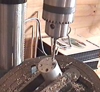
13 September 1999 After fixing my lathe I trued up both ends of the aluminum rod that is to be the intake venturi and reed-valve seat.
These holes were drilled at a 30 degree angle -- a procedure I was not too sure about because I thought the drill might wander a little when addressing the face of the work so far off-square. The method I finally used was to punch the hole positions then lightly counter-sink the punch-marks with a drill perpendicular to the surface before rotating the table of the drill press to 30 degrees and drilling the pilot holes. The final 6mm holes were then drilled to a depth that meant they all joined up at a focal point in the center of the bar. You may note the lack of measurements at this stage -- I have to admit that when I'm designing and developing I tend to fly by the seat of my pants and use the "looks about right" technique for deciding on dimensions. I can hear you cringing from here :-) Rest assured that I do carefully measure things when it's necessary to ensure that holes line up and components fit together though.
Please remember I'm new to this stuff so if you have any comments or criticisms about the methods or techniques used then please feel free to throw them at me. Later this week I hope to finish this part of the engine by drilling a hole from the other end of the unit to join up with the eight intake port holes then turn that out into a venturi on the lathe.
|
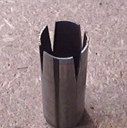
 I marked and drilled the eight holes which carry the air-fuel mixture into the
combustion chamber.
I marked and drilled the eight holes which carry the air-fuel mixture into the
combustion chamber.
 I'll go back and measure things when I know it all works so as to provide those
interested in building their own pulse jet with a set of working blueprints.
I'll go back and measure things when I know it all works so as to provide those
interested in building their own pulse jet with a set of working blueprints.
|
September 12 Today has been very frustrating! My lathe has been behaving erratically for a few weeks and just as I sat down to turn up the aluminum intake venturi and reed-valve seat/retainer for the pulse jet, the damned lathe stopped completely.
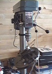
I guess I'll just go back to work and try to claw back the hours mid-week once I've had a chance to get a replacement. Oh.. but I did get around to unpacking and assembling my new drill press and it's a beauty. Not even Chinese! (unless the Republic of Taiwan counts :-) I also took a few minutes to update the links page with some more interesting sites.
5 September 1999
I've collected together the following materials at this stage:
I also have some lumber to build a test stand and a plastic fuel tank and flexible plastic piping to connect it to the engine. I will probably add some kind of thrust measuring facility to the test stand using a spring and graduated scale. Unfortunately labor day here in New Zealand isn't until late October so I don't have the benefit of a holiday weekend to do much more on this project today -- and it's now late Sunday afternoon so you won't see any additions to this page until next weekend.
|
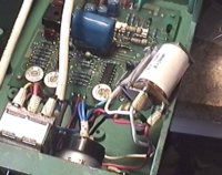 As you'll see from the accompanying picture -- I have delved into the
atrociously constructed electronics of the beast and found the relay to
have an open-circuit winding. And, wouldn't you know it -- amongst the
myriad of boxes of electronic componentry accumulated over the last 20 years
I don't have, a double-poll 20K ohm, 220V relay so that puts an end to this
weekend's construction work.
As you'll see from the accompanying picture -- I have delved into the
atrociously constructed electronics of the beast and found the relay to
have an open-circuit winding. And, wouldn't you know it -- amongst the
myriad of boxes of electronic componentry accumulated over the last 20 years
I don't have, a double-poll 20K ohm, 220V relay so that puts an end to this
weekend's construction work.
 I've also collected all the raw materials (right) I think I'll need and started
clearing the junk off my workbench. Given the nature of this project I also
checked that my fire extinguisher was fully loaded and ready for the operational
trials.
I've also collected all the raw materials (right) I think I'll need and started
clearing the junk off my workbench. Given the nature of this project I also
checked that my fire extinguisher was fully loaded and ready for the operational
trials.
|