A Home Workshop Guide
Last Updated: 13 February, 2002
Why Build A Metal Spinning Lathe?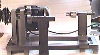 I guess I could have gone out and bought a commercial wood-lathe and used that
for metal spinning but I have had an old budget-priced drill press sitting here
for a couple of years and I really wanted to put (at least parts of) it to
good use.
So, I scrounged the motor, pulleys, drive belt, power wiring/switch and bearings from this drill press and built a lathe around them!
Design Considerations Other than the legacy components, there was the issue of exactly what I had sitting in my metal rack and scrap bin -- which wasn't much. Apart from the main-shaft, just about everything on this lathe was made from 25mm square or 25x50mm CRS 1020 steel bar stock. There are no castings -- it's just cut to size and bolted together. The main spindle and the backplate were turned from 1214 free-machining steel which is much nicer to work with than plain old 1020. The chips from 1214 are small and blunt and -- unlike the razor sharp shards that come off 1020 when it's milled or turned. If you're planning to turn anything out of steel, do yourself a favor and get some free-machining stock such as 1214 or 12L14.
Tools Used
General Layout Unlike a metal-turning lathe, these machines don't have a cross-slide or compound, so they don't need accurately ground ways and all the extra parts and machining that such pieces entail. In effect, these lathes consist of little more than a headstock and a place to rest your tools.
The Headstock The basic design of the headstock is very simple -- it's two pieces of 50x25mm (2"x1") which hold the shaft bearings and are separated by a piece of 25mm (1") square down the middle so as to make an 'I' beam. The holes which retain the bearings were drilled to 14mm and then bored out to 36mm, the outside diameter of the bearings used. I'm not too happy with the results here actually -- I was trying out new carbide inserts and didn't find a satisfactory combination of insert, sfm and feed rate until I'd done the first hole -- but they're okay. The 36mm hole doesn't go right through of course -- it's recessed to 12mm -- the thickness of the bearings. Rather than just bolt the two pieces of 50x25 to the central 25x25mm center-piece, I milled 1mm deep slot in the 50x25 pieces so that the centerpiece was held snugly in place.
There are then two horizontal pieces of 50x25 bar which bolt to the headstock so as to connect it firmly to the bed of the lathe. These have 25x25mm notches cut in the bottom edge (these were hacksawed and then squared/finished with the mill). They also have a 1mm deep slot milled in them so that the headstock is firmly keyed in place. I was very pleased with the level of accuracy achieved with machining the headstock components -- they all fit together very snugly -- requiring just a light hammer-tap to seat everything in its groove. After that you can pick the whole thing up and it won't fall apart -- even without the bolts in place.
The Main-shaft
A smaller 22mm OD collar was machined to fit very snugly over the end of the main-shaft and it is secured with a grub-screw. Of course the parts of the shaft where the bearings sit also had to be machined for a close interference fit so that the shaft doesn't spin inside the bearing. Finally, the end of the shaft to which the backplate is attached also needed a close interference fit so that it didn't have room to wobble or slip. I was thinking of turning a taper here to ensure good centering and maximum grip -- but I decided to try a straight shaft first and see how that turned out.
The Backplate So -- the backplate is simply a place where the necessary form can be bolted or keyed to stop it shifting about. I decided to turn up the backplate from a 20mm thick piece of 100mm diameter 1214 steel I had sitting on the shelf. This makes a pretty heavy item but the extra thickness ensures good alignment on the shaft and resistance to skewing due to the high side-loads imposed by the spinning operation. To make it easier to center the form on the backplate, I turned a number of concentric rings into the face of the backplate. The backplate is retained on the main shaft by an 8mm high-tensile bolt that screws into a matching thread in the end of the shaft. One of the nicest things about making this part was that I had to turn it in two operations on the 7x10. The jaws in my 4" 4-jaw chuck had to be reversed to hold it and then, having turned one face and half the edge, I had to remount it and set the runout to zero. Any axial run-out would have manifested itself as a discontinuity or lip along the edge of the backplate where the two machining operations didn't line up. After spending a little more time than usual, I got the plate lined up so that the dial-indicator didn't budge and, although there's a slight visible difference between the two halves, there's no discernable lip or edge to the touch.
The Bed There's no need for precision ground and hardened ways to guide a saddle and cross-slide -- it's all pretty basic stuff. Since the tooling on these lathes is hand-held, there's no need for absolute rigidity in the lathe bed either -- so I just used 25mm (1") square section laid out into a rectangle.
The Tailstock To acommodate different length forms, the tailstock needs to be able to be shifted along the bed -- as with a regular lathe so the base was made from a piece of 25mmx50mm (1"x2") CRS into which two slots were milled so that it would ride on the 25mm (1") sq pieces that make up the bed. Milling these slots was a good test of the RF30's ability to put its 2HP motor to work. I used a 16mm 4-flute cobalt end-mill running at around 500 RPMs to move the metal. I took off 2mm at a time and, although there was some vibration (as you'd expect), it breezed through without any problems.
The tailstock vertical is another piece of (you guessed it) 25mm x 50mm (1"x2") CRS. At the top of the tailstock is the adjustment screw and live-center needed to provide the clamping force. The clamping mechanism consists of a 10mm cap-head bolt which runs in a threaded hole drilled at the top of the vertical. It is locked in position by another cap-head bolt (6mm) that screws down and presses a brass pad onto the main bolt. Because the alignment of the tailstock is critical to accurate work-holding, the decision was made to use an adjustable mounting system for affixing the vertical to the tailstock cross-member. This was done by mounting the vertical to a smaller cross-piece that is in turn bolted to the main cross-member. The height can now be adjusted by shimming, the angle and horizontal alignment can be set by loosening the mounting screws, moving and retightening. The live-center was made using one of the other spindle bearings out of the drill press. The static side was machined from 6061 aluminum and screws onto the end of the 10mm bolt which passes through the tailstock. It also holds the bearing. The rotating part of the live-center is also turned from 6061 and is designed to be easily changed. I wanted to be able to use different sized centers for different sized forms.
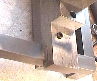
The final piece is the clamping bar which holds the tailstock from sliding along the bed as clamping pressure is applied through the live-center. This was made from a single piece of 25mm (1") sq which has the ends milled as you'll see in the picture. This cross-piece simply clamps the tailstock to the bed by tightening two bolts that pass through from above. There was no point in building any fancy cam-lock mechanism for this (although it would not be too hard) because the talistock is only moved when changing forms.
The Toolrest By the time I got to this part of the lathe, the prospect of having to mill out another cross-piece and clamping bar was all to much -- so instead the toolpost clamps to the closest rail of the lathe bed -- halving the number of machining operations required. A 50x25mm (2"x1") piece of CRS serves as the post and it has a slot milled into it so that it's a nice snug (but sliding) fit over the bed-rail. Another smaller piece of 50x25 is also slotted and fits on the other side -- the clamping pressure being provided by two bolts that pull the two pieces together with the bed rail firmly held between. On top of the toolpost is a cross-piece made from 25x25 (1"x1") which is retained by a single bolt so that it can be swiveled and locked to make tool manipulation easier against the form. Several holes have been drilled and vertical pins inserted to give leverage points for the hand-held tooling.
The Drive System I was going to just weld up a motor mount -- but ended up doing things the hard way and milling up a little mounting block that is in turn bolted to a mounting plate that is (in turn) bolted to the lathe bed. I could have made this thing in about half the time if I'd welded instead of bolting everything. The motor is a 1/2 HP unit and speed is changed simply by moving the belt to the required grooves on the pulleys. I'm probably breaking about a million different laws by not having a cover over the pulley -- but that's another project. If I'm brave/stupid enough to attack a rapidly spinning disk of stainless steel with a metal bar while the whole lot spins around at several thousand RPMs then a little old pulley isn't my biggest worry ;-) Unfortunately the belt that came as standard is a piece of crap and seems to have been spliced in about four places. This makes it alternately stiff and flexible -- something that causes vibration. I'll replace it shortly with a decent quality belt.
Do Yourself A Favor! I'm still nursing a sore shoulder from all that manual hacksawing. And... if you're a masochist like I am -- have a good supply of nice, sharp 18 tpi blades on hand. Don't be miserly -- cutting steel with a blunt blade is a dumb thing to do -- it wastes time and invites poor results. And don't think you're going to be able to move even a little lathe like this around too easily. It's actually heavier than my 7x10 metal-turning lathe! I've already started spinning up some aluminum and stainless using this lathe and although I'm pretty low on the learning curve, it does the job just fine and it's already become an indispensible part of my workshop.
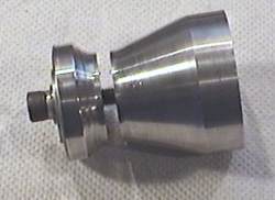
Coming Soon(ish): Learning To Spin! There aren't a lot of good tutorials or metal spinning info sites on the Web so I'm hoping I can perhaps create some interest. Until I get these pages up, those interested in spinning might want to check out this guide (PDF file) which has some great stuff. Meanwhile -- here are some of the intake venturis I've been spinning for my pulsejet engines.
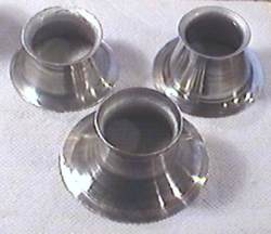
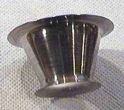
These were spun from 1.2mm 1100 alloy aluminum which was anealed by heating and quenching prior to use -- because the local merchant couldn't supply in anything other than H12 temper.
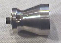
In order to spin a shape like this which would otherwise get "stuck" on the
form, it's necessary to make the form so that it can be broken into
two parts for extraction purposes.
|
|

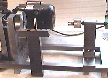 Obviously some of the design constraints and parameters were set by the parts
I was re-using from the drill press. This did introduce some less than
optimal limitations -- such as the use of 19mm bearings, meaning that
the mains-shaft of the lathe was also limited to 19mm in diameter. If this
turns out to be too weak I'll just go buy some bigger bearings and make a new
shaft.
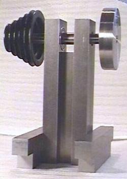 I decided to start with the headstock and designed it so that the center
of the backplate would sit 180mm (7 inches) above the lathe-bed. This
provides enough clearance to spin a disk of metal 14 inches in diameter --
plenty large nough for my purposes and probably more than the little 1/2HP
motor is capable handling.
 I can't imagine any casting being more rigid than this beefy item once
it's all tightened up snugly.
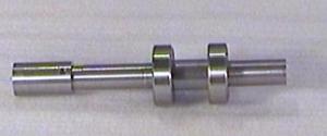 Firstly -- because the pulley salvaged from my drill press was designed to fit
on a 22mm shaft -- but the bearings only allowed the maximum thickness for the
shaft on that side of the bearings to be 19mm, I had to make it in two parts.
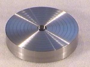 With a metal-spinning lathe there is no need for a chuck. Instead of gripping
the work as you would on a metal lathe, the work is actually clamped between
a specially turned form and a live-center on the tailstock.
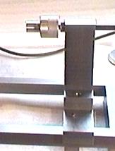 The job of the tailstock is to apply the clamping pressure that holds the
metal disk (which is to be spun into the final shape) firmly against
the face of the form.
 A sharp center is used to firmly secure the wood when I'm turning up the initial
form for later use in the spinning process.
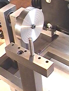 As mentioned above, the tooling for spinning or wood-turning is hand-held --
so this requires the addition of a toolrest.