Last updated 8 March, 2001
|
Thrust Is Fine But... Having built my jet engine, complete with afterburner, it became apparent that "raw thrust" is perhaps not the most effective way to use the power generated. Let's face it, pushing a lot of hot air and flames out of a steel pipe may look and sound pretty impressive but it's sometimes more than a little impractical. Even the holy grail of home-built turbojet builders "the jet powered go-kart" will have pretty limited acceleration and hill-climbing abilities when you compare the 10-40lbs of thrust generated against the 200 odd lbs of kart and driver. The problem is that a small column of fast-moving air (the jet exhaust) is not a particularly efficient way to propel a relatively slow-moving vehicle. The solution is to convert that exhaust stream into shaft-horsepower which can be used to drive the wheels of the kart (or turn a generator, pump or whatever).
Extracting Shaft Horsepower
A 12:1 reduction gearbox will convert 72,000 RPMs of turbine speed down to 6,000 RPMs of shaft speed while also boosting the torque by a factor of 12 (gearbox losses not withstanding).
Whether the ball-races will stand up to the high temperatures and revs remains to be seen. The ones I'm using are rated to 40,000 RPMs so, at least in the first instance, I'll keep the final power-shaft revs down to 3,300 (for a turbine speed of just under the rated maximum the bearings can handle). Proper ceramic bearings that are designed to handle the high revs and high temperatures of this environment are really expensive -- about US$100 a pair, so if I can get away with plain old $5 units (even if they have to be replaced at regular intervals) then I'll be really happy.
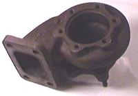
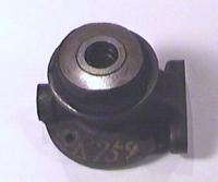
Machining The Bearing Housing Well, in reality, I simply reproduced the external dimensions of the core casting of the original turbocharger but bored it to suitable dimensions for carrying the new ball bearings and a steel sleeve against which the turbo's rear shaft-seal can run.
I'm not sure that aluminum is the right material for this job -- it won't melt but it has a high rate of thermal expansion which might cause problems with distortion at high temperatures -- we'll just have to wait and see I guess. An oil feed for the bearings was provided by drilling some fine feed holes which are fed with a mix of synthetic oil and kerosene that is misted into the bearing shaft tunnel by a bleed from the engine's compressor. At present this is a total-loss lube system -- which is to say that the oil is not recycled but just drains into a collection tank. The oil-flow is designed to be very low so a small tank should last for several runs.
Cutting The Gears
Still To Be Done.. Watch this page for updates!
|
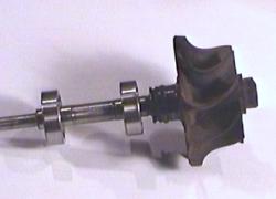 This second turbine will be driven by the engine exhaust (sorry, the
afterburner has to go). Exhaust gasses will turn this wheel at high RPMs -- albeit
quite a bit lower than the main turbine wheels/shaft. Instead of this second
turbine driving a compressor, it will drive a reduction gear-set to produce
torque at sensible (0-6,000 RPMs) speed.
This second turbine will be driven by the engine exhaust (sorry, the
afterburner has to go). Exhaust gasses will turn this wheel at high RPMs -- albeit
quite a bit lower than the main turbine wheels/shaft. Instead of this second
turbine driving a compressor, it will drive a reduction gear-set to produce
torque at sensible (0-6,000 RPMs) speed.
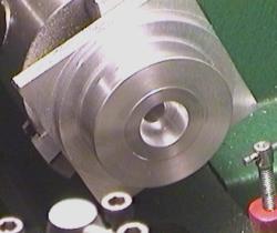
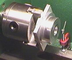 I turned a big block of aluminum into a bearing housing by simply removing all
the bits of metal that didn't look like a bearing housing :-)
I turned a big block of aluminum into a bearing housing by simply removing all
the bits of metal that didn't look like a bearing housing :-)
|