Last updated 22 February, 2001
|
NEW! -- First kart chasis tests under pulse-jet power (1 February 2001)
The Holy Grail?
Well, in order to make some use of the power shaft addition to my gas turbine engine I figured I might as well build such a vehicle.
The Components After checking out prices for reasonably sized pneumatic wheels I discovered that the cheapest option was buying a couple of cheap "made in China" loading trolleys. These cost me NZ$59 each (giving me two wheels), whereas exactly the wheels sold alone would have cost NZ$45 a pop! Buying the two trolleys saved me $56 over buying the wheels individually -- AND I got about 18 feet of steel tubing and two axles as well. It will be interesting to see how well these wheels stand up to the punishment a gokart gives them. Although they have twin ball bearings and, by virtue of coming off a loading trolley, should be expected to handle the weight of a kart, I'm left wondering how well they'll hold up under the side-loads that might be encountered when cornering.
The chasis will be built from some 1 inch square section tubing I've got lying around and the various bits of pipe I'll be able to scavange from the trolley frames.
Basic Design There'll be no clutch, mainly because the free-turbine attached to the engine's power-shaft also acts as a torque converter. Gearing will be fixed and I've calculated the intial ratios to give me a top speed of 20Km/H (around 12 MPH) -- no point in getting too carried away because this thing won't have disk brakes (hmm.. brakes, maybe I'd better add at least some kind of braking mechanism onboard!). However, at this stage I have absolutely no idea whether my small gas-turbine engine will have enough power to get a gokart up to this kind of mind-altering speed -- or even budge it into any kind of forward motion at all. And while I think of it, I'd better make sure that I have the output shaft turning the right direction so that the kart doesn't take off backwards -- that would be a real disapointment.
Engine Modifications I'm also giving some thoughts to the issue of adding baffles to the oil tank to ensure there's no way the pump will run dry during high-speed cornering (oh yeah... I'm allowed to dream :-) Another thing I'm not sure about is the amount of back-pressure that a stalled power turbine might produce when the kart is stationary and the engine is at idle. My solution to this (if it becomes a problem) is to have a manually operated wastegate on the power-turbine which is linked to the throttle. When the engine is idling the wastegate will be open, allowing the gases to bypass the power turbine -- but when the throttle is increased above idle the wastegate will be closed and all the gasses will be made to flow through the turbine.
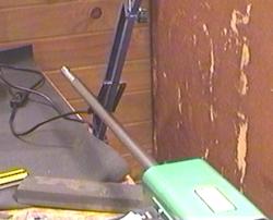
Latest News As you can see from the picture on the right -- this is only just going to fit into the free space I have available on my workshop floor. Goodness knows how I'm going to get it in and out without moving a whole lot of gear out of the way. It's actually bigger than I thought it would be -- but that's good because I want plenty of space for mounting the engine(s) and working on them in position without having to remove them to get to the important bits for maintenance or modification. This will in effect be my new engine test-bed.
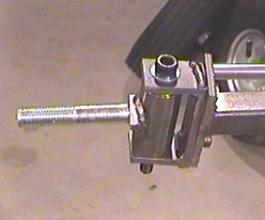
Previously I've given the front-end an 8 degreen kingpin inclination and 8 degrees of caster -- which is adjustable to 12 degrees. The kingpin inclination provides the self-centering and the caster angle provides stability at speed while also ensuring that the wheels operate at the best camber angle when turning.
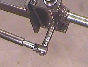
The system is designed to allow for easy adjustment of the steering alignment and the effective connection point of the tie-rod is offset from the steering arm so as to provide the correct ackerman angles.
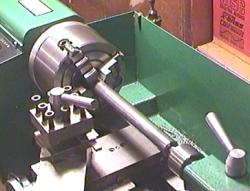
The rear axle is turned from a solid bar of steel which is a meter long (about 39 inches) -- something you might think is a little too large for my small lathe that only has 10 inches between centers.
The result was a whole lot of axle passing through the lathe spindle and hanging out the back -- but it worked very well and allowed me to turn down the ends of the axle to suit the wheel hubs, and thread them for a retaining nut.
Previously
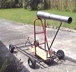
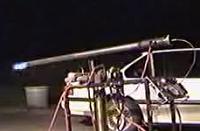
A Rolling Test-bed For My Pulse-Jet Engines I'll be starting the tests by mounting one of my largest pulse-jet engines (75 pounds of thrust) on the kart which should easily get the thing up to 40 mph.
The sparks coming out the back of this early prototype are actually fragments of the reed-valves as they hammer themselves to death -- not an uncommon problem with these engines and something which has been a problem for all pulse-jet designers (until now ;-) My new pulse-jet design is much shorter than this, has optional direct fuel-injection, and uses my new electroplated V-shaped reed-valve system which produces much more power and lasts far longer than the old "petal" valves commonly used on these engines. I'm actually thinking of patenting the special process I've developed for creating long-life, high-efficiency valves because it makes such a huge difference to performance and reliability. Having searched all the online and off-line literature I have access to, I've seen nothing else even remotely like this process -- probably because development of pulse-jet engines seems to completely stopped with the commercial development of the gas-turbine in the late 1950's. |
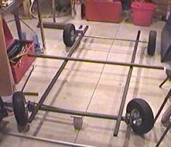 I've now laid out the chasis in preparation for welding to begin in earnest.
 Part of the reason this is taking so long is that I'm grossly over-designing
and over-engineering this thing -- it's a bad habit I know!
Part of the reason this is taking so long is that I'm grossly over-designing
and over-engineering this thing -- it's a bad habit I know!
 As you can see from these pictures, I used my "big" 4-jaw chuck (mainly
because it has a bigger hole through it than the 3-jaw) and pushed as much
through as I could while still allowing the live-center to be installed.
As you can see from these pictures, I used my "big" 4-jaw chuck (mainly
because it has a bigger hole through it than the 3-jaw) and pushed as much
through as I could while still allowing the live-center to be installed.
|