A Wooden Pulsejet?
Last Updated: 6 November, 2002

|
Testing New Ideas One of the most daunting problems facing those of us who experiment with pulsejet engines is that of creating and testing new designs. Many of the things which look good on paper simply don't work in practice -- but you can spend a lot of time and effort find out this fact. If you're mathematically inclined and have access to the right software you can use computational fluid dynamics to model your proposed design. Unfortunately such software and its use is often way beyond the means of the casual experimenter. This just leaves the option of cutting, forming and welding lots of metal -- sometimes trying dozens of variations on a theme -- only to find that your great idea was flawed right from the start. With this in mind I some time ago created the poor-man's flow simulator, a device that's been put to good use in testing many of my own ideas. To demonstrate it, I built a model of the proposed valveless intake system documented on this page. This system is not only able to prove the fact that my assertions in respect to which way the gases would flow were correct -- but it would also allow me to design and test the various angles, curves and relative dimensions without cutting a single piece of metal.
How Does It Work? It consists of four main parts:
The flow indicators are simply short lengths of thread tied to pins that are then driven into the backboard at strategic locations. This thread will be blown by the airflow and show which way the flows are moving. They can also give a good indication as to flow-speed because they tend to vibrate more quickly in faster flows. To use this rig, the profiles are simply placed on the backboard, the glass sheet is then placed on the top, and air is blown through the relevant entry-point. I've taken an MPEG video of this system in action, demonstrating the new Coanda-effect valveless intake system. This will show you how the rig, and the intake system works.
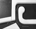 Click image to view 420Kbyte MPEG video Using this simple setup I was able to move the intake diamond and other elements around and, in a few short minutes, establish the optimal relationship between these parts. Air was then directed into the input-tube opening and similar adjustments were made to optimize the flow during this phase of the engine's operation. From this testing I was able to produce a compromise configuration which, even with my "guesstimate" angles and radiuses, reduces the unwanted flows to just 15% or so of the total flows. Based on this testing, I'm pretty sure that the proposed valveless intake system would work very well if it were optimized further. When I get time I'll cut some new pieces of wood continue work on this. There it is folks, -- simple gasflow modeling on a budget.
Limits and Caveats Perhaps the biggest limitation is that it is simply a 2-dimensional model and doesn't properly represent the effects of a 3-dimensional design. Despite this, I still consider the rig to be a valuable piece of equipment for those who want to try a myriad of different ideas but don't want to waste a lot of time and money building full-blown prototypes each time.
|
|