Jet engine technologies for interested amateurs
Last Updated: 27 November, 2001

Cutting Gears For The Turboshaft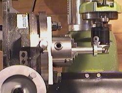 In order to turn the anticipated 70K rpms of the gas-turbine engine's
power turbine to a more sedate speed suitable for driving a conventional
generator, pump or (in this case) gokart, it is necessary to add some gearing.
In order to turn the anticipated 70K rpms of the gas-turbine engine's
power turbine to a more sedate speed suitable for driving a conventional
generator, pump or (in this case) gokart, it is necessary to add some gearing.
Finding gears of suitable size, pitch and ratios turned out to be a very difficult task so I figured I'd make my own -- creating an interesting exercise in using my mill. The method I'm using is a technique that utilizes a single-point cutter mounted in a boring head. The gear blank is turned to size on the lathe and then mounted on a special shaft I turned up to do the job. This effectively clamped the gear blank very firmly and then the shaft itself was placed in the 3-jaw chuck on my 8" rotary table.
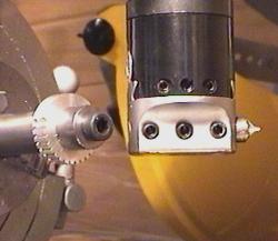
The Single-point Cutter
To make the job a little quicker and easier, I used a 16mm end-mill to form the basic cutter shape while the drill-rod was still in its anealed state. I then hardened and tempered the drill-rod and ground the final cutter shape using a combination of my bench-grinder and my Dremel. I have to admit that it's not quite as easy a job as I'd hoped it would be. Getting the cutter form symetrical and accurately mating it to an existing gear required a lot of patience and really showed up just how old my eyes are getting. However, after an hour or so of empirical grinding I finally achieved a shape I was happy with and I proceeded to cut my first gear.
NOTE: -- as I rapidly discovered, a cutter made from hardened
drill rod is only suitable for use on soft, free-machinging metals such as aluminum and
perhaps brass. When I tried my hardened drill rod cutter on steel it lasted
exactly 1 tooth before becoming too blunt to cut cleanly.
To allow me to cut
steel gears without having to grind a relatively large piece of toolsteel I
made a simple adaptor by drilling a piece of 12mm drill rod so that I could
insert 5mm toolsteel ground to shape and retained by a set-screw.
This new cutter setup, using quality Swedish toolsteel for the cutting point,
has now cut some 5 gears from 1214 steel (a total of around 200 teeth) and
doesn't yet need resharpening.
Cutting The Teeth
The ideal way to rotate the gear blank is using a rotary indexer -- a fancy device that allows you to rotate the work by a regular fixed angular amount. Unfortunately rotary indexers are hideously expensive so I just calculated the number of degrees between teeth and used the dials on my rotary table to the same effect. This is pretty easy when you're working in even multiples of 360 degrees but can be a real error-prone pain if not (hence the reason that people are prepared to pay so much money for fancy rotary indexers eh?).
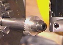
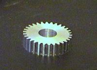
The gear I created on this test-run is a 30-tooth unit that will actually see service in my lathe. The other lathe gears are steel but the aluminum one seems not to be wearing inordinately and it's a size that I've needed on several occasions but never had. Now I will move on and start the steel gears -- which will be case-hardened after they're cut. I've never case-hardened anything before so I'll document the process here for others who will be able to learn from my mistakes.
I used a commercial product called Kasenite and just followed the instructions which were very straight forward and simple. Before risking a set of gears, I practiced on a plain piece of 1214 steel just to make sure I wasn't going to mess things up. The steel was heated until it had a medium-red glow using a slightly carburizing flame from my oxy-acetylene torch and then dipped into the Kasenite powder and rolled about so as to pick up a good thick coating. The torch was then reapplied to the work to heat it up again. Just a word of warning here -- they don't mention it in the instructions but this stuff produces a bright yellow flare when heated. While it's not bright enough to cause any permanent eye damage, it will produce "spots" in your vision if you stare at it without any kind of protection. I used the filtered goggles I use for oxy-welding so that I could see what was going on without squinting. After returning it to a mid-red heat, the work was then plunged into a quench bath of plain cold water and swirled around. Testing the resulting piece of steel with a file showed that it was indeed well case-hardened -- the results were quite astounding. I then hardened two steel gears and found the following: 1. You have to be careful heating a gear with a direct flame -- the tips of the teeth heat up far more quickly than the hub of the gear. When I noticed that this was happening I actually placed the gears onto a small plate of HRS and heated the plate from below until I got everything up to a nice red heat. 2. You can save a little money by just case-hardening the teeth themselves rather than the whole gear. I did this by rolling the red-hot gearwheel through the Kasenite so that only the edges picked up a coating. 3. Allow for thermal distortion. After case-hardening, the mesh of my gears had altered slightly. Not enough to worry too much about - but it appears that they grew slightly and this required the spacing between centers to be increased by a few thou in order to get nice smooth operation. Another thing to consider when using a single-point hand-ground cutter is that the form of the teeth thus created is unlikely to be perfect. Subsequently I have found that it makes quite a difference if you allow the gears to "bed in" by running together for half an hour or so in their un-hardened state. This wears off the high-spots and produces a much smoother mesh. If you don't do this before you case-harden then they'll probably never bed in properly and the result will be more vibration and power loss due to the imperfections.
Other Things I've Case Hardened Why didn't I just use drill-rod? Simple -- I needed the punches urgently and didn't have any drill-rod of a sufficiently large diameter. I've also ground and polished number of tools for my metal spinning lathe from 1214 steel and finished them by case-hardening. The results have been excellent.
|
 So -- I took the cheap way out and ground my own single-point cutter from
drill-rod.
So -- I took the cheap way out and ground my own single-point cutter from
drill-rod.
 I figured it would be a good idea to practice on a soft, easily machined material
like aluminum before cutting the actual steel gears I plan to use in the
turboshaft gearbox.
I figured it would be a good idea to practice on a soft, easily machined material
like aluminum before cutting the actual steel gears I plan to use in the
turboshaft gearbox.
 I cut the first gear in two passes (although it could easily be done in one pass
when machining aluminum) and it took about 15 minutes -- around
30 seconds per tooth.
I cut the first gear in two passes (although it could easily be done in one pass
when machining aluminum) and it took about 15 minutes -- around
30 seconds per tooth.
|