Flight-tested, advanced technology
Last Updated: February, 2009

How's it done?
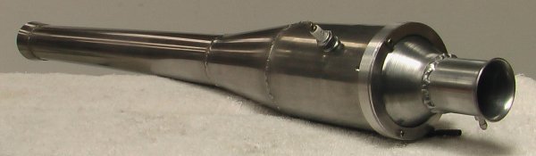
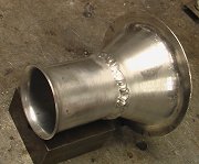
The body In the case of the PJ8C, there are four separate sections to the engine and they're all cut from 0.5mm stainless steel sheet. Once cut to size and shape, these four sections are rolled to form the tubes and cones which make up the body. This rolling is performed using a set of slip-rolls with care being taken to ensure that the resulting parts are as round as possible.
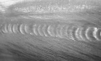
The tubes and cones are TIG welded using a 1.6mm tungsten and an inert argon
atmosphere. Welding stainless steel sheet this thin is very difficult as even
the smallest mistake can result in hole or an ugly mess. I use a small overlap
and fusion-welding techniques to get the lightest but strongest results.
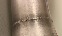
After welding, the body is pickled -- a process that uses a very corrisive mix of acids to remove the dark iron oxides formed near the weld area by the heat of the welding process. Since pickling leaves the stainless steel with a matte finish, the bodies are then lightly polished to restore some lustre.
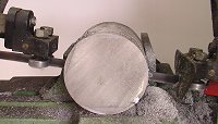
A hole is drilled in the center and it is bolted to a mandrel so that the rest of the machining operations can be performed.
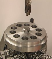
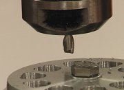
The plate is now moved from the lathe to a rotary table on the mill where ten holes are drilled at 36 degree intervals. These are the inlet holes over which the reed valve sits.
After being returned to the lathe, a small truncated cone is turned in the center of the plate on the front side. This mates with another cone to form the intake cone that directs the incoming air and fuel towards the holes in the valve-plate. Several other holes are also drilled into the valveplate, including the four holes that be used to retain the plate in the body and the holes for the pressure-tap.
The intake cone
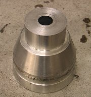
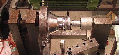
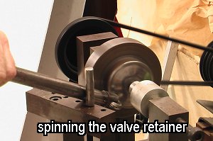
The diffuser cone section is spun from a disk of aluminum. This creates an extremely
rigid and light component. The spinning is done on my own purpose-built spinning
lathe.
The tuned intake tube is made from aluminum tubing and carefully flared at the
inlet end using a purpose-built flaring tool. It is then drilled to accept the
atomizer jet then welded to the spun diffuser cone. Yes, the TIG welder
comes in handy once again. More jigs are used to ensure accurate alignment and,
believe it or not, welding this aluminium is
actually easier than welding the very thin stainless from which the body is made.
A ring of thicker aluminum slips over the intake tube/cone and effectively clamps the flange on the diffuser against the front of the valveplate. It is drilled to take some cap-head screws. The fuel atomizer jet is held in place using a single M4 nut. This method of forming the intake venturi was chosen because it produces a part that is far lighter than results from turning the whole thing from a solid block of aluminum as was done for the prototype engine.
The pressure tap The two parts are TIG welded together.
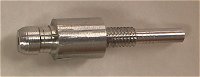
Unlike the aluminum retainers used in some engines, the this stainless steel component will not melt, break or warp despite the high combustion temperatures and vibration inherent to the inside of a pulsejet engine. It is also much ligher than the equivalent aluminum part.
Finishing things off The 10mm hole is also drilled for the sparkplug.
A custom-designed nut is also macined up and tapped to retain the sparkplug. The fuel atomizer jet is also turned and drilled from aluminum.
That's it! As you can now see, although pulsejet engines are intrinsically very simple in design and construction, to build one to a reasonable standard of quality and consistency takes many different steps, the right equipment, plus a number of specially built jigs and tools. It actually takes more than a full day to make each engine, which is why I only make small batches and only when time allows.
|
 Each piece is now cleaned to remove traces of metal scale and oil from the rollers
then placed in the welding jigs. These jigs are essential to ensure the best
quality welds and the minimum of distortion during the welding process. They
also serve to stop the back-side of the weld from forming carbide intrusions
into the pipes and cones.
Each piece is now cleaned to remove traces of metal scale and oil from the rollers
then placed in the welding jigs. These jigs are essential to ensure the best
quality welds and the minimum of distortion during the welding process. They
also serve to stop the back-side of the weld from forming carbide intrusions
into the pipes and cones.
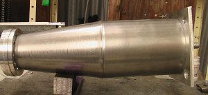 Once the tubes and cones are welded down their seams, they're positioned (again
using jigs) in careful alignment and welded together to form the body.
Once the tubes and cones are welded down their seams, they're positioned (again
using jigs) in careful alignment and welded together to form the body.
 The valve-plate
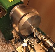
 After being turned to the correct thickness, the portion which sits inside the
combustion chamber is turned down to a tight fit and a slight taper is turned
onto the back edge so that it's easier to slide into the body.
After being turned to the correct thickness, the portion which sits inside the
combustion chamber is turned down to a tight fit and a slight taper is turned
onto the back edge so that it's easier to slide into the body.
 Once the drilling is complete, the shape of the round holes are modified by a
milling operation which increases the valved area.
Once the drilling is complete, the shape of the round holes are modified by a
milling operation which increases the valved area.
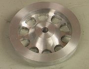 The plate is now fliped over and the front-face has a ring milled in it.
 The intake venturi/diffuser
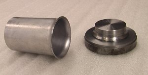
 The valve retainer
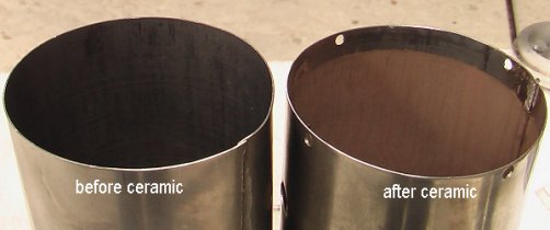 A special ceramic coating is then applied to the inside of the combustion chamber
and part of the tailpipe section using an in-house technique that has been
refined over several months. This coating bonds to the surface of the stainless
with a tenatious grip that even the heat and pressure of combustion won't
affect.
A special ceramic coating is then applied to the inside of the combustion chamber
and part of the tailpipe section using an in-house technique that has been
refined over several months. This coating bonds to the surface of the stainless
with a tenatious grip that even the heat and pressure of combustion won't
affect.
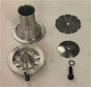 Here are the valve-head/intake components including:
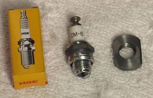 Sparkplug and machined retaining nut.
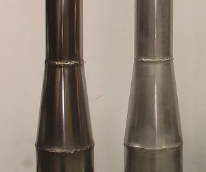 Welded pulsjet bodies. The one on the right has been pickled to remove weld
scale and the one the left has then been polished to restore lustre.
Welded pulsjet bodies. The one on the right has been pickled to remove weld
scale and the one the left has then been polished to restore lustre.
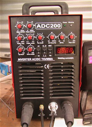 The TIG welder used for much of the construction.
|