Also check out my home-made Quick-change Toolpost (21 Aug 2001)
 Why Make This Mod?
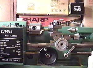
Like most purchasers of the Chinese 10x7 minilathe (as sold by Harbor Freight,
Grizzly and a host of other machinery shops), I was disappointed with the
general finish of my machine.
Most annoying was the slop and backlash in the cross-slide and the occasional
stiffness of the compound slide.
The solution to getting a silky-smooth, zero backlash compound slide was to
add a ball bearing to the compound shaft.
 What's Wrong With The Original?
I found that my compound offered me the choice of a free-turning mechanism with
backlash or a tight handle and minimal backlash. Neither of these options
was acceptable to me so I took the thing apart to see how it was built.
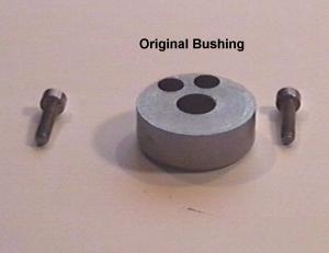
Horror! There were no bearings -- just a simple bushing against which the face
of the handle rubbed in order to provide the thrust when winding the handle
counter-clockwise.
What's worse, the hole in my handle had been drilled slightly oversize so that
tightening the set-screw produced an ever so slight canting of the handle on
the shaft. This meant that at some positions of a full rotation, the handle
was so tight as to be hard to turn, while at other positions it was so loose
as to allow the compound to be moved back and forth by several thou.
I guess I could have simply turned up a new handle with a smaller hole -- but
that would still have meant a compromise between backlash and friction, so I
decided to replace the existing bushing with a ball bearing.
 The Bearing Housing
This starts life as simple replacement for the standard bushing (above) but I
turned mine out of aluminum rather than steel and starting with a length of 38 mm bar stock,
turning it down so that it was a couple of millimeters bigger than the old bush.
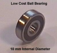
The actual outside diameter of your bearing housing will be dictated by the OD
of the bearing you use. Rather than have everyone scurrying around trying to find
an exact match for the bearing I used, I suggest you simply find one that has
a 10 mm internal diameter (that's the diameter of the threaded shaft on my lathe,
check your own, it may be different).
If you're turning your bearing housing from aluminum like I did, turn down
your bar-stock to allow at least 1.5 mm of "meat" around the bearing when
it's fitted. If you use steel you might get away with just 1 mm.
This is pretty simple machining but here's the sequence of steps I took when
turning up my bearing holder:
- Cut off a piece of bar stock (35 mm - 38 mm in diameter) that is long
enough to allow the chuck jaws to get a good grip but still leave room for
the cut-off tool when you're parting the turned/bored housing from the rest.
- Mount the stock in the chuck (note: you'll probably have to use the other
pair of chuck jaws that should have come with your lathe because we're talking
about 35 mm stock here and that's beyond the standard jaws.)
- Face the end of the bar.
- Drill a 10 mm hole lengthwise at least 20 mm deep. I start with a small
(3.5 mm) pilot drill and go up in 3mm increments until I reach the desired size.
- Turn the outside of the stock down to the required diameter. The bearing
I used has a 30 mm outside diameter so I turned down the bar to 34 mm so as
to allow for the 2 mm of "meat" I spoke about above once the bearing hole
is bored out.
- Take your favorite boring tool (if you don't have one, now's a good time
to grind one from HSS) and open up the 10mm hole to match the outside
diameter of your bearing. In my case this was 30 mm so I opened up the hole
to 29.9 mm and then took an ever so light finishing skim so that there was still
a small amount of friction when seating the bearing. You can check that the
bearing fits in snuggly -- lightly oiling it will help you get it in and out.
If the bearing appears to get stuck at this stage -- don't panic. You can either
warm the bearing housing slightly or use a hooked piece of wire to alternately
pull from different points around the circumference of the inner ring of the
bearing. Note that if you need to remove the bearing housing from the lathe
at this time, be sure and place a small punch-mark next to lathe jaw number 1
so you can replace it in the same position.
Remember to make the bored recess deep enough to take the bearing. My bearing
was 9 mm thick so I bored the 29.9 mm recess 9 mm deep. On reflection I should
have made it 9.5 for reasons I'll explain later.
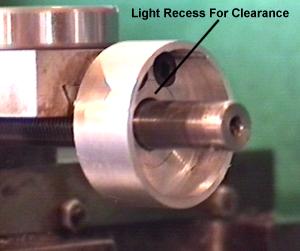
- Now bore a further slight recess on the inner face of the recess as
shown in the picture on the right. This extra recess is to ensure
that the inside part of the bearing (the bit that turns with the shaft)
doesn't rub against the back of the bearing housing. Just a few thou
should be plenty of clearance.
- At this point you should part the bearing holder from the rest of the bar.
The parting cut should be taken so as to allow 6 mm of metal behind the bearing.
ie: if your bearing is 9 mm deep like mine, then part the bearing holder with
a cut 15 mm from the face of the work. Actually, if your parting tool leaves
rough edges like mine you might want to allow an extra mm so that you can
turn the work around and face it with your regular cutting tool to make it nice
and smooth. It's also handy to allow this extra metal for smoothing if you're
the kind that hesitates to cut right through 34 mm of bar using a parting tool --
because then you can finish off the cut with a hacksaw, turn it around and face-off
the hacksaw marks.
- To mark the exact position of the two holes into which the mounting bolts
fit, simply place the newly made bearing housing face down on the bench (so
the flat face is topmost), place the old bushing on top of it and then slip
your 10 mm drill bit through the holes so that they're both lined up.
Then you can take a drill bit that is a snug fit in the bolt holes on the
old bushing and push it into the holes and twist. This will leave a mark on
the new part underneath at exactly the right place. Punch and drill these
holes.
- Now you need to countersink the bolt-holes so that the heads can recess
flush with the back-surface of the bearing holder. If you have a mill then
just thrown in the right sized two-flute endmill and the job is easy. Just don't
go too deep, you only have a couple of mm to spare here.
If you don't have a mill then you can simply use a regular twist-drill bit --
but you'll have to be even more careful not to go too deep because of the
angle of the point. If you're at all worried you can always buy some spare
4 mm cap-head hex screws and grind the heads down a little so the countersink
doesn't have to be too deep. In fact, it's a good idea to use replacement screws
because the originals will be too long and would need to be cut shorter.
I'm afraid I'm one of those people who hates to make irreversible modifications --
always preferring to keep the original parts intact so that if something goes
wrong I can restore the machine to its original condition.
- Now place the bearing holder back in the lathe and open up the 10 mm hole
you drilled to about 11 mm. This will give you some room to play with when
lining up the bearing housing onto the compound slide.
Assembling
At this point the new bearing holder is complete and all we need do is install
it, complete with bearing.
First screw the new bearing housing to the compound -- but just tighten the
screws lightly so as to allow for some "maneuvering."
 Slide the bearing over the shaft and snug it into the housing. If the bearing
isn't perfectly lining up with the housing you can give the housing a little
tap and the lightly tightened mounting bolts should allow it to slip into position.
Slide the bearing over the shaft and snug it into the housing. If the bearing
isn't perfectly lining up with the housing you can give the housing a little
tap and the lightly tightened mounting bolts should allow it to slip into position.
Once you're happy with the alignment, push the compound along the shaft and
with any luck the shaft will push the bearing out of the housing. Then pull
the bearing off the shaft and tighten down the mounting screws.
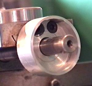
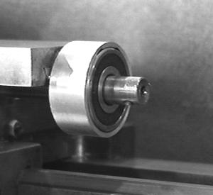
Now you can put the bearing back in for good and things should look like the
picture on the right (sorry it's black and white but the color balance on
the original was awful).
 Modifying The Handle
If you use the original handle without modification then you'll still get binding
because its flat face will rub equally against the inner (rotating) and outer
(stationary) rings of the bearing.
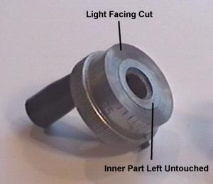
To make things work properly you must relieve a band on the outer area of
the handle as in the picture to the right.
Only a tiny amount needs to be taken off -- just enough to provide a tiny clearance.
Now you'll recall that in step 6 of the turning instructions (above), I mentioned
that I should have recessed my bearing an extra half a millimeter -- and here's
why....
As you'll see from the picture of the finished job, the small relief cut that
you take on the face of the handle actually creates a gap between the handle
and the bearing housing. While it's not important, you may wish to have no gap --
in which case, having the front of the bearing housing half a mm proud of the
bearing itself will allow you to cut an extra relief nearer the edge of the
handle so that it almost touches.
Question -- how are you going to work on the compound handle if your lathe
doesn't have a compound handle?
Answer -- I simply gripped the shaft with a small set of vice grips. Another
alternative is to simply leave the original handle on while you turn up a new one.
 Putting The Handle Back On
The handle should go back on now -- although it won't fit as far onto the shaft
as it did before because the bearing housing is likely deeper than the old bush.
If you find that the shaft doesn't reach far enough inside to allow the set-screw
to engage you have two choices: You can drill and tap a new hole for the set
screw or you can turn up a new handle.
Personally I'd opt for the latter.
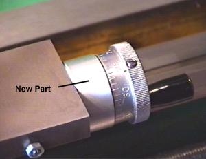
The image on the right is "the finished job" -- albeit I have yet to engrave a
reference mark on the bearing housing against which the graduations on
the handle can be aligned.
I'm very pleased with the results of this modification, it's meant that I now
use the compound a lot more than I used to -- for a while I did almost all
my carriage movement with the "big wheel" but that's not an option when you're
cutting threads or need to make very fine facing cuts to a specific depth.
A couple of friends who were not impressed with the compound on my minilathe
before are now annoyed that my tiny Asian machine feels better than their
own larger and more expensive machines (gloat, gloat).
 If anyone's really stuck for a suitable 10 mm bearing I can probably provide
you with bearing type I used -- they're very cheap, I paid just US$5 for
mine. However, bear in mind that I live in New Zealand so, even by airmail,
it will take a couple of weeks to arrive and postage may be twice the cost
of the part.
If anyone's really stuck for a suitable 10 mm bearing I can probably provide
you with bearing type I used -- they're very cheap, I paid just US$5 for
mine. However, bear in mind that I live in New Zealand so, even by airmail,
it will take a couple of weeks to arrive and postage may be twice the cost
of the part.
I don't want to get into the bearing-supply market so if someone in the USA
finds a suitable part number and supplier, let me know and I'll post it here.
Many thanks to Mike Meagher who did some research and came up with the
following part numbers for bearings:
|
NTN |
6200LLBC33/5C
| |
Fafnir |
200PP
| |
SKF |
6200-2RS
| |
NSK |
6200VV
| |
Koyo |
6200-2RS
| |
FAG |
6200.2RSR
| |
MRC |
200SZZ
|
Mike says the bearings are a very common size available from any good
bearing supply company and offers the URL
http://www.mcmaster.com
as a suggestion.
According to their catalog the prices are:
|
5972K41 |
$3.54
|
| |
61653K74 |
$21.34
|
Stainless Steel
| |
6661K101 |
$6.94
|
Higher precision
|
|
|